Marine pump
-
Marine Fire Pump
-
Marine Emergency Fire Pump
-
Marine Ballast Water Pump
-
Marine Fuel Pump
-
Marine Lubricating Oil Pump
-
Marine Bilge Pump
-
Marine Sewage Pump
-
Marine Fresh Water Pump
-
Marine General Pump
-
Marine Cargo Oil Pump
-
Marine Hand Pump
-
Marine Pump Parts
-
Marine Centrifugal Pump
-
Marine Screw Pump
-
Marine Gear Pump
-
Marine Vortex Pump
-
Marine Ejector Pump
-
Marine Diaphragm Pump
-
Marine Piston Pump
-
Marine Cooling Water Pump
Chemical pump
Urban pump
Other pump
Civil Pump
Submersible Pump
Contact us
Fushi Pump Chongqing Co., Ltd
Address: No. 11, Tianxing Avenue, ShuangQiao Industrial Park, Chongqing,China
E-mail: material@hiseamarine.com
Tel: +86-23-67956606
Fax: +86-23-67956622
Mobil: +86-19332298771
CB Marine Horizontal Centrifugal Domestic Pump
Date:2022-07-08Views:

CB Marine Horizontal Centrifugal Domestic Pump
Overview
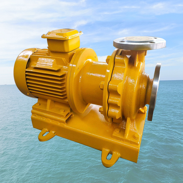
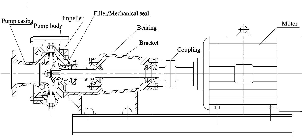
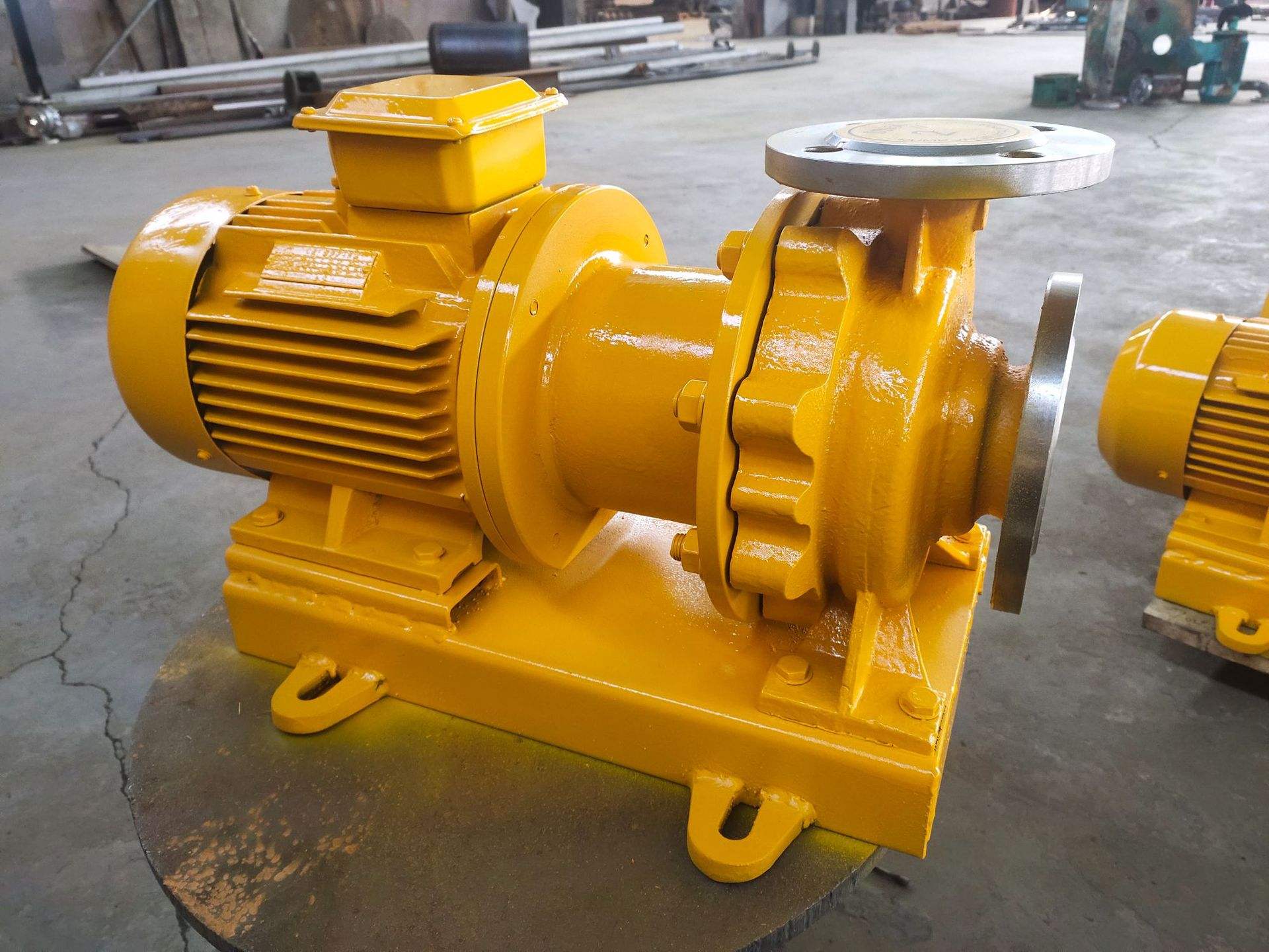
CB Series of single-stage single-suction cantilever centrifugal pump, used for carrying water and physical and chemical properties similar to the use of liquid water, the liquid temperature not exceeding 85degrees C, applicable to ships pumping bilge, fire, health and other fresh water or sea water, as well as factories, mines, city and rural irrigation water supply use. The CB type marine centrifugal pump is a type BA pump improvement products, it uses copper alloy, stainless steel impeller shaft, a mechanical seal or packing seal of two seal structure. Performance parameter and with the original BA type pump the same, but on the reliability of marine pump, pump parts General requirements higher than the general BA type pump. This Series of products after the upgrade, derived from: CBH Series (install relay device after the absorption process can reach 15m) and CBX Series (the installation of sliding vane vacuum pump variable for self-priming pump).
Model Explanation 11/2CB(BA)H/X-25A(B)
11/2—Inlet diameter was 25 except an integer value after
CB—Single stage single-Inlet cantilever centrifugal pump
H—Max suction head type
X—Suction type
25—Specific speed divided by10 and the integral number .
A(B)—Impeller processed with 1(2)time cutting.
Structural Specifications

The excellent design of our company's engineers, components made of high-quality materials can extend the life of the pump, reduce the frequency of maintenance, operation stability in complex environments, but it also cause different prices. If you need more details about this, you can click on the news or send an email to ask us
Performance Parameter:
(The following are only the partial parameters.In addition, please provide the parameter of the marine pump you need and we can customize the suitable type for you.)
CB(BA)H/X | 50HZ/2900RPM | 60HZ/3500RPM | 50HZ/60HZ | ||||||||
Type | Capacity (m3/h) | Head (m) | Motor Power (kW) | Capacity (m3/h) | Head (m) | Motor Power (kW) | Efficiency (%) | Suction Head (m) | Impeller Dia. (mm) | Weight (kg) | Inlet/out dia. (mm) |
11/2CB-6 | 6 | 20.3 | 1.5 | 7.2 | 29.2 | 3 | 44 | 6.6 | 128 | 26 | 40/32 |
11 | 17.4 | 13.2 | 25.1 | 55.5 | 6.7 | ||||||
14 | 14 | 16.8 | 20.2 | 53 | 6 | ||||||
11/2CB-6A | 5 | 16 | 1.5 | 6 | 23 | 2.2 | 38 | 6.5 | 115 | 26 | 40/32 |
9.5 | 14.2 | 11.4 | 20.5 | 51.5 | 6.9 | ||||||
13.5 | 11.2 | 16.2 | 16.1 | 50 | 6.1 | ||||||
11/2CB-6B | 4.5 | 12.8 | 1.1 | 5.4 | 18.4 | 1.5 | 35 | 6.4 | 105 | 26 | 40/32 |
9 | 11.4 | 10.8 | 16.4 | 49 | 7 | ||||||
13 | 8.8 | 15.6 | 12.7 | 45 | 6.3 | ||||||
2CB-6 | 10 | 34.5 | 4 | 12 | 49.7 | 7.5 | 50.6 | 8.2 | 162 | 43 | 50/40 |
20 | 30.8 | 24 | 44.4 | 64 | 7.2 | ||||||
30 | 24 | 36 | 34.6 | 63.5 | 5.7 | ||||||
2CB-6A | 10 | 28.5 | 3 | 12 | 41 | 5.5 | 54.5 | 8.2 | 148 | 43 | 50/40 |
20 | 25.2 | 24 | 36.3 | 65.6 | 7.2 | ||||||
30 | 20 | 36 | 28.8 | 64.1 | 5.7 | ||||||
2CB-6B | 10 | 22 | 2.2 | 12 | 31.7 | 4 | 54.9 | 8.2 | 132 | 43 | 50/40 |
20 | 18.8 | 24 | 27.1 | 65 | 7.2 | ||||||
25 | 16.3 | 30 | 24.2 | 64 | 6.6 | ||||||
2CB-9 | 11 | 21 | 2.2 | 13.2 | 30.2 | 4 | 56 | 8 | 127 | 38 | 50/40 |
20 | 18.5 | 24 | 26.6 | 68 | 6.8 | ||||||
25 | 16 | 30 | 23 | 66 | 6 | ||||||
2CB-9A | 10 | 16.8 | 2.2 | 12 | 24.2 | 3 | 54 | 8.1 | 117 | 38 | 50/40 |
17 | 15 | 20.4 | 21.6 | 65 | 7.3 | ||||||
22 | 13 | 26.4 | 18.7 | 63 | 6.5 | ||||||
2CB-9B | 10 | 13 | 1.5 | 12 | 18.7 | 2.2 | 51 | 8.1 | 106 | 38 | 50/40 |
15 | 12 | 18 | 17.3 | 60 | 7.6 | ||||||
20 | 10.3 | 24 | 14.8 | 62 | 6.8 | ||||||
3CB-6 | 30 | 62 | 15 | 36 | 89.3 | 22 | 54.4 | 7.7 | 218 | 116 | 80/50 |
45 | 57 | 54 | 82.1 | 63.5 | 6.7 | ||||||
60 | 50 | 72 | 72 | 30 | 66.3 | 5.6 | |||||
70 | 44.5 | 84 | 64.1 | 64 | 4.7 | ||||||
3CB-6A | 30 | 45 | 11 | 36 | 64.8 | 15 | 55 | 7.5 | 192 | 116 | 80/50 |
40 | 41.5 | 48 | 59.8 | 62 | 7.1 | ||||||
50 | 37.5 | 60 | 54 | 64 | 6.4 | ||||||
60 | 30 | 72 | 43.2 | 18.5 | 59 | 5.8 | |||||
3CB-9 | 30 | 35.5 | 7.5 | 36 | 51.1 | 11 | 62.5 | 7 | 168 | 60 | 80/50 |
45 | 32.6 | 54 | 46.9 | 71.5 | 5 | ||||||
55 | 28.8 | 66 | 41.5 | 68.2 | 3 | ||||||
3CB-9A | 25 | 26.2 | 5.5 | 30 | 37.7 | 7.5 | 63.7 | 7 | 145 | 60 | 80/50 |
35 | 25 | 42 | 36 | 70.8 | 6.4 | ||||||
45 | 22.5 | 54 | 32.4 | 71.2 | 5 | ||||||
3CB-13 | 32.4 | 21.5 | 4 | 38.9 | 31 | 7.5 | 76 | 6.5 | 132 | 41 | 80/50 |
45 | 18.8 | 54 | 27.1 | 80 | 5.5 | ||||||
52.2 | 15.8 | 62.6 | 22.8 | 75 | 5 | ||||||
3CB-13A | 29.5 | 17.4 | 4 | 35.4 | 25.1 | 5.5 | 75 | 6 | 120 | 41 | 80/50 |
39.6 | 15 | 47.5 | 21.6 | 80 | 5 | ||||||
48.6 | 12 | 58.3 | 17.3 | 74 | 4.5 | ||||||
3CB-13B | 28 | 13.5 | 2.2 | 33.6 | 19.4 | 4 | 63 | 5.5 | 110 | 41 | 80/50 |
34.2 | 12 | 41 | 17.3 | 65 | 5 | ||||||
41.5 | 9.5 | 49.8 | 13.7 | 62 | 4 | ||||||
4CB-6 | 65 | 98 | 55 | 78 | 141.1 | 75 | 63 | 7.1 | 272 | 138 | 100/80 |
90 | 91 | 108 | 131 | 68 | 6.2 | ||||||
115 | 81 | 138 | 116.6 | 68.5 | 5.1 | ||||||
135 | 72.5 | 162 | 104.4 | 66 | 4 | ||||||
4CB-6A | 65 | 82 | 37 | 78 | 118.1 | 55 | 63.2 | 7.1 | 250 | 138 | 100/80 |
85 | 76 | 102 | 109.4 | 67.5 | 6.4 | ||||||
105 | 69.5 | 126 | 100.1 | 75 | 68.5 | 5.5 | |||||
125 | 61.5 | 150 | 88.7 | 66 | 4.6 | ||||||
4CB-8 | 70 | 59 | 30 | 84 | 85 | 37 | 64.5 | 5 | 218 | 116 | 100/80 |
90 | 54.2 | 108 | 78.1 | 69 | 4.5 | ||||||
109 | 47.8 | 130.8 | 68.8 | 45 | 69 | 3.8 | |||||
120 | 43 | 144 | 61.9 | 66 | 3.5 | ||||||
4CB-8A | 70 | 48 | 22 | 84 | 69.1 | 37 | 67 | 5 | 200 | 116 | 100/80 |
90 | 43 | 108 | 61.9 | 69 | 4.5 | ||||||
109 | 36.8 | 130.8 | 53 | 65 | 3.3 | ||||||
4CB-12 | 65 | 37.7 | 15 | 78 | 54.3 | 22 | 72 | 6.7 | 178 | 108 | 100/80 |
90 | 34.6 | 108 | 49.8 | 78 | 5.8 | ||||||
120 | 28 | 144 | 40.3 | 74.5 | 3.3 | ||||||
4CB-12A | 60 | 31.6 | 11 | 72 | 45.5 | 18.5 | 70 | 6.9 | 163 | 108 | 100/80 |
85 | 28.6 | 102 | 41.2 | 76 | 6 | ||||||
110 | 23.3 | 132 | 33.6 | 73.5 | 4.5 | ||||||
4CB-18 | 65 | 22.6 | 11 | 78 | 32.5 | 15 | 75 | 5 | 143 | 65 | 100/80 |
90 | 20 | 108 | 28.8 | 78 | |||||||
110 | 17.1 | 132 | 24.6 | 74 | |||||||
4CB-18A | 60 | 17.2 | 7.5 | 72 | 24.8 | 11 | 74 | 5 | 130 | 65 | 100/80 |
80 | 15.2 | 96 | 21.9 | 76 | |||||||
95 | 13.2 | 114 | 19 | 71.1 | |||||||

Precautions for use
1. The maximum working pressure of the pump and the connected pipeline is ≤1.6MPa, and the pressure at the suction port of the pump + the pump head is ≤1.6Mpa. (If the working pressure of the pump system is greater than 1.6MPa, it should be put forward separately when ordering, so that we can use cast steel for the over-current parts and connecting parts of the pump during manufacture).
2. The ambient temperature does not exceed 50°C, the altitude does not exceed 1000 meters, and the relative humidity does not exceed 95%.
3. The conveying medium is clear water or other liquids with similar physical and chemical properties to clear water. (The conveying medium contains fine particles, which should be specified separately when ordering, so that we can assemble the wear-resistant mechanical seal.)
4. Before installing the pump, carefully check whether there are hard objects (such as stones, iron particles, etc.) in the pump flow channel that affect the operation of the pump, so as to avoid damage to the impeller and pump body when the pump is running.
5. The weight of the pipeline should not be added to the pump during installation, and there should be their own support bodies to avoid the deformation of the pump and affect the running performance and life.
6. The anchor bolts must be tightened during installation to avoid the impact of vibration on the pump performance during startup.
7. For the convenience of maintenance and safe use, a regulating valve is installed on the inlet and outlet pipelines of the pump and a pressure gauge is installed near the pump outlet to ensure the operation within the rated head and flow range, to ensure the normal operation of the pump and the growth of the pump. service life of the pump.
8. After installation, turn the pump shaft, the impeller should have no friction noise or stuck phenomenon, otherwise the pump should be disassembled to check the cause.
