Marine pump
-
Marine Fire Pump
-
Marine Emergency Fire Pump
-
Marine Ballast Water Pump
-
Marine Fuel Pump
-
Marine Lubricating Oil Pump
-
Marine Bilge Pump
-
Marine Sewage Pump
-
Marine Fresh Water Pump
-
Marine General Pump
-
Marine Cargo Oil Pump
-
Marine Hand Pump
-
Marine Centrifugal Pump
-
Marine Screw Pump
-
Marine Gear Pump
-
Marine Vortex Pump
-
Marine Ejector Pump
-
Marine Diaphragm Pump
-
Marine Piston Pump
-
Marine Cooling Water Pump
Chemical pump
Industrial Pumps
Other pump
Civil Pump
Submersible Pump
Contact us
Fushi Pump Chongqing Co., Ltd
Address: No. 11, Tianxing Avenue, ShuangQiao Industrial Park, Chongqing,China
E-mail: Sales1@fspumps.com
Tel: +86-23-67956606
Fax: +86-23-67956622
Mobil: +86-19332298771
CLH Marine Vertical Centrifugal Pump
Date:2025-03-10Views:
CLH Marine Vertical Centrifugal Pump
Overview
CLH type pump is in accordance with ISO international standards and the design of a single stage, single suction, level inlet and outlet of the centrifugal pump, the motor shaft and the pump shaft flange connection is convenient to disassemble. Can be used as various ship ballast pump, bilge pump, drainage pump, cooling pump, fire pump, and is also suitable for the petrochemical pipe City, high-rise building water and circulation system of the booster pump. Transmission fluid temperature not exceeding 75℃.
Model Explanation CLH 50-160 (I) A(B, C)
CLH—Marine vertical sea water pump
50—Inlet and outlet diameter 50 mm
160—Nominal diameter of impeller 160mm
I—Flow classification
A(B, C)—Impeller processed with 1(2, 3)cutting
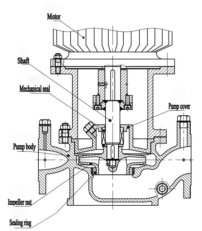
Structural Specifications

CLH
Performance Parameter
CLH | 50HZ | 60HZ | 50HZ/60HZ | ||||||||
Type | Capacity (m3/h) | Head (m) | Speed (rpm) | Motor power (kW) | Weight (kg) | Capacity (m3/h) | Head (m) | Speed (rpm) | Motor power (kW) | (NPSH)r (m) | Efficiency (%) |
15-80 | 1.1 | 8.5 | 2900 | 0.18 | 17 | 1.3 | 12.2 | 3500 | 0.25 | 2.3 | 26 |
1.5 | 8 | 1.8 | 11.5 | 34 | |||||||
2 | 7 | 2.4 | 10.1 | 34 | |||||||
20-110 | 1.8 | 16 | 2900 | 0.37 | 25 | 2.2 | 23 | 3500 | 0.75 | 2.3 | 25 |
2.5 | 15 | 3 | 21.6 | 34 | |||||||
3.3 | 13.5 | 4 | 19.4 | 35 | |||||||
20-125 | 1.8 | 21 | 2900 | 0.75 | 35 | 2.2 | 30.2 | 3500 | 1.1 | 2.3 | 30 |
2.5 | 20 | 3 | 28.8 | ||||||||
3.3 | 18.6 | 4 | 26.8 | ||||||||
20-160 | 1.8 | 33 | 2900 | 1.1 | 29 | 2.2 | 47.5 | 3500 | 1.5 | 2.3 | 19 |
2.5 | 32 | 3 | 46.1 | 25 | |||||||
3.3 | 30 | 4 | 43.2 | 23 | |||||||
25-110 | 2.8 | 16 | 2900 | 0.55 | 26 | 3.4 | 23 | 3500 | 0.75 | 2.3 | 34 |
4 | 15 | 4.8 | 21.6 | 42 | |||||||
5.2 | 13.5 | 6.2 | 19.4 | 41 | |||||||
25-125 | 2.8 | 20.6 | 2900 | 0.75 | 28 | 3.4 | 29.7 | 3500 | 1.1 | 2.3 | 28 |
4 | 20 | 4.8 | 28.8 | 36 | |||||||
5.2 | 18 | 6.2 | 25.9 | 35 | |||||||
25-125A | 2.5 | 17 | 2900 | 0.75 | 27 | 3 | 24.5 | 3500 | 1.1 | 2.3 | 35 |
3.6 | 16 | 4.3 | 23 | ||||||||
4.6 | 14.4 | 5.5 | 20.7 | ||||||||
25-160 | 2.8 | 33 | 2900 | 1.5 | 39 | 3.4 | 47.5 | 3500 | 2.2 | 2.3 | 24 |
4 | 32 | 4.8 | 46.1 | 32 | |||||||
5.2 | 30 | 6.2 | 43.2 | 33 | |||||||
25-160A | 2.6 | 28.5 | 2900 | 1.1 | 34 | 3.1 | 41 | 3500 | 1.5 | 2.3 | 22 |
3.7 | 28 | 4.4 | 40.3 | 31 | |||||||
4.9 | 26 | 5.9 | 37.4 | 29 | |||||||
32-100 | 4.5 | 12.5 | 2900 | 0.55 | 27 | 5.4 | 18 | 3500 | 0.75 | 2 | 44 |
32-100(I) | 3.75 | 13.2 | 2900 | 0.75 | 32 | 4.5 | 19 | 3500 | 1.1 | 2 | 48 |
5.3 | 12.5 | 6.4 | 18 | 54 | |||||||
8.3 | 11.3 | 10 | 16.3 | 53 | |||||||
32-125 | 3.5 | 22 | 2900 | 0.75 | 28 | 4.2 | 31.7 | 3500 | 1.1 | 2.3 | 40 |
5 | 20 | 6 | 28.8 | 44 | |||||||
6.5 | 18 | 7.8 | 25.9 | 42 | |||||||
32-125A | 3.1 | 17.6 | 2900 | 0.55 | 28 | 3.7 | 25.3 | 3500 | 0.75 | 2.3 | 39 |
4.5 | 16 | 5.4 | 23 | 43 | |||||||
5.8 | 14.4 | 7 | 20.7 | 41 | |||||||
32-160 | 5 | 32 | 2900 | 1.5 | 39 | 6 | 46.1 | 3500 | 2.2 | 2.3 | 44 |
32-160A | 4 | 25 | 2900 | 1.1 | 38 | 4.8 | 36 | 3500 | 1.5 | 2 | 34 |
32-160(I) | 4.4 | 33.2 | 2900 | 2.2 | 47 | 5.3 | 47.8 | 3500 | 3 | 2 | 34 |
6.3 | 32 | 7.6 | 46.1 | 40 | |||||||
8.3 | 30.2 | 10 | 43.5 | 42 | |||||||
32-200 | 4.5 | 50 | 2900 | 3 | 55 | 5.4 | 72 | 3500 | 4 | 2 | 32 |
32-200A | 2.8 | 44.6 | 2900 | 3 | 74 | 3.4 | 64.2 | 3500 | 4 | 2 | 34 |
4 | 44 | 4.8 | 63.4 | 40 | |||||||
5.2 | 42.7 | 6.2 | 61.5 | 42 | |||||||
32-200(I) | 4.4 | 50.5 | 2900 | 4 | 43 | 5.3 | 72.7 | 3500 | 5.5 | 2 | 26 |
6.3 | 50 | 7.6 | 72 | 33 | |||||||
8.3 | 48 | 10 | 69.1 | 35 | |||||||
40-100 | 4.4 | 13.2 | 2900 | 0.55 | 32 | 5.3 | 19 | 3500 | 0.75 | 2.3 | 48 |
6.3 | 12.5 | 7.6 | 18 | 54 | |||||||
8.3 | 11.3 | 10 | 16.3 | 53 | |||||||
40-100A | 3.9 | 10.6 | 2900 | 0.37 | 32 | 4.7 | 15.3 | 3500 | 0.55 | 2.3 | 46 |
5.6 | 10 | 6.7 | 14.4 | 52 | |||||||
7.4 | 9 | 8.9 | 13 | 51 | |||||||
40-125 | 4.4 | 21 | 2900 | 1.1 | 34 | 5.3 | 30.2 | 3500 | 1.5 | 2.3 | 41 |
6.3 | 20 | 7.6 | 28.8 | 46 | |||||||
8.3 | 18 | 10 | 25.9 | 43 | |||||||
40-125A | 3.9 | 17.6 | 2900 | 0.75 | 33 | 4.7 | 25.3 | 3500 | 1.1 | 2.3 | 40 |
5.6 | 16 | 6.7 | 23 | 45 | |||||||
7.4 | 14.4 | 8.9 | 20.7 | 41 | |||||||
40-160 | 4.4 | 33 | 2900 | 2.2 | 47 | 5.3 | 47.5 | 3500 | 3 | 2.3 | 35 |
6.3 | 32 | 7.6 | 46.1 | 40 | |||||||
8.3 | 30 | 10 | 43.2 | 40 | |||||||
40-160A | 4.1 | 29 | 2900 | 1.5 | 43 | 4.9 | 41.8 | 3500 | 2.2 | 2.3 | 34 |
5.9 | 28 | 7.1 | 40.3 | 39 | |||||||
7.8 | 26.3 | 9.4 | 37.9 | 39 | |||||||
40-160B | 3.8 | 25.5 | 2900 | 1.1 | 38 | 4.6 | 36.7 | 3500 | 1.5 | 2.3 | 34 |
5.5 | 24 | 6.6 | 34.6 | 38 | |||||||
7.2 | 22.5 | 8.6 | 32.4 | 37 | |||||||
40-200 | 4.4 | 51 | 2900 | 4 | 74 | 5.3 | 73.4 | 3500 | 5.5 | 2.3 | 26 |
6.3 | 50 | 7.6 | 72 | 33 | |||||||
8.3 | 48 | 10 | 69.1 | 32 | |||||||
40-200A | 4.1 | 45 | 2900 | 3 | 62 | 4.9 | 64.8 | 3500 | 4 | 2.3 | 26 |
5.9 | 44 | 7.1 | 63.4 | 31 | |||||||
7.8 | 42 | 9.4 | 60.5 | 30 | |||||||
40-200B | 3.7 | 38 | 2900 | 2.2 | 52 | 4.4 | 54.7 | 3500 | 3 | 2.3 | 24 |
5.3 | 36 | 6.4 | 51.8 | 29 | |||||||
7 | 34.5 | 8.4 | 49.7 | 28 | |||||||
40-250 | 4.4 | 82 | 2900 | 7.5 | 105 | 5.3 | 118.1 | 3500 | 15 | 2.3 | 24 |
6.3 | 80 | 7.6 | 115.2 | 28 | |||||||
8.3 | 74 | 10 | 106.6 | 28 | |||||||
40-250A | 4.1 | 72 | 2900 | 7.5 | 98 | 4.9 | 103.7 | 3500 | 15 | 2.3 | 24 |
5.9 | 70 | 7.1 | 100.8 | 28 | |||||||
7.8 | 65 | 9.4 | 93.6 | 27 | |||||||
40-250B | 3.8 | 61.5 | 2900 | 5.5 | 77 | 4.6 | 88.6 | 3500 | 7.5 | 2.3 | 23 |
5.5 | 60 | 6.6 | 86.4 | 27 | |||||||
7 | 56 | 8.4 | 80.6 | 26 | |||||||
40-100(I) | 8.8 | 13.2 | 2900 | 1.1 | 34 | 10.6 | 19 | 3500 | 1.5 | 2.3 | 55 |
12.5 | 12.5 | 15 | 18 | 62 | |||||||
16.3 | 11.3 | 19.6 | 16.3 | 60 | |||||||
40-100(I)A | 8 | 10.6 | 2900 | 0.75 | 32 | 9.6 | 15.3 | 3500 | 1.1 | 2.3 | 53 |
11 | 10 | 13.2 | 14.4 | 60 | |||||||
14.5 | 9 | 17.4 | 13 | 58 | |||||||
40-125(I) | 8.8 | 21.2 | 2900 | 1.5 | 38 | 10.6 | 30.5 | 3500 | 2.2 | 2.3 | 49 |
12.5 | 20 | 15 | 28.8 | 58 | |||||||
16.3 | 17.8 | 19.6 | 25.6 | 57 | |||||||
40-125(I)A | 8 | 17 | 2900 | 1.1 | 33 | 9.6 | 24.5 | 3500 | 1.5 | 2.3 | 48 |
11 | 16 | 13.2 | 23 | 57 | |||||||
14.5 | 14 | 17.4 | 20.2 | 56 | |||||||
40-160(I) | 8.8 | 33 | 2900 | 3 | 56 | 10.6 | 47.5 | 3500 | 4 | 2.3 | 45 |
12.5 | 32 | 15 | 46.1 | 52 | |||||||
16.3 | 30 | 19.6 | 43.2 | 51 | |||||||
40-160(I)A | 8.2 | 29 | 2900 | 2.2 | 47 | 9.8 | 41.8 | 3500 | 3 | 2.3 | 44 |
11.7 | 28 | 14 | 40.3 | 51 | |||||||
15.2 | 26 | 18.2 | 37.4 | 50 | |||||||
40-160(I)B | 7.3 | 23 | 2900 | 1.5 | 43 | 8.8 | 33.1 | 3500 | 2.2 | 2.3 | 43 |
10.4 | 22 | 12.5 | 31.7 | 50 | |||||||
13.5 | 20.5 | 16.2 | 29.5 | 49 | |||||||
40-200(I) | 8.8 | 51.2 | 2900 | 5.5 | 85 | 10.6 | 73.7 | 3500 | 7.5 | 2.3 | 38 |
12.5 | 50 | 15 | 72 | 46 | |||||||
16.3 | 48 | 19.6 | 69.1 | 46 | |||||||
40-200(I)A | 8.3 | 45 | 2900 | 4 | 75 | 10 | 64.8 | 3500 | 5.5 | 2.3 | 37 |
11.7 | 44 | 14 | 63.4 | 45 | |||||||
15.3 | 42 | 18.4 | 60.5 | 45 | |||||||
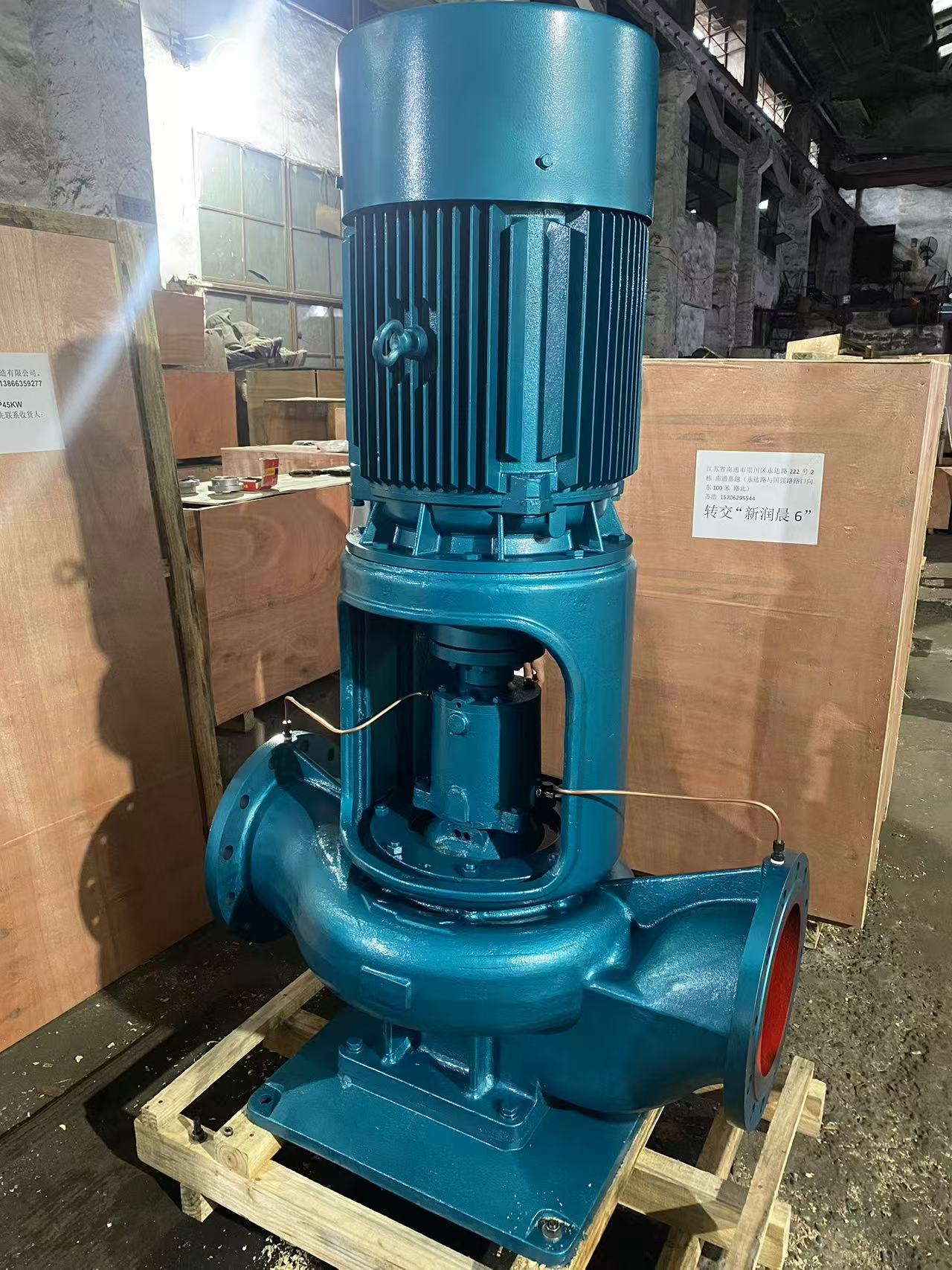
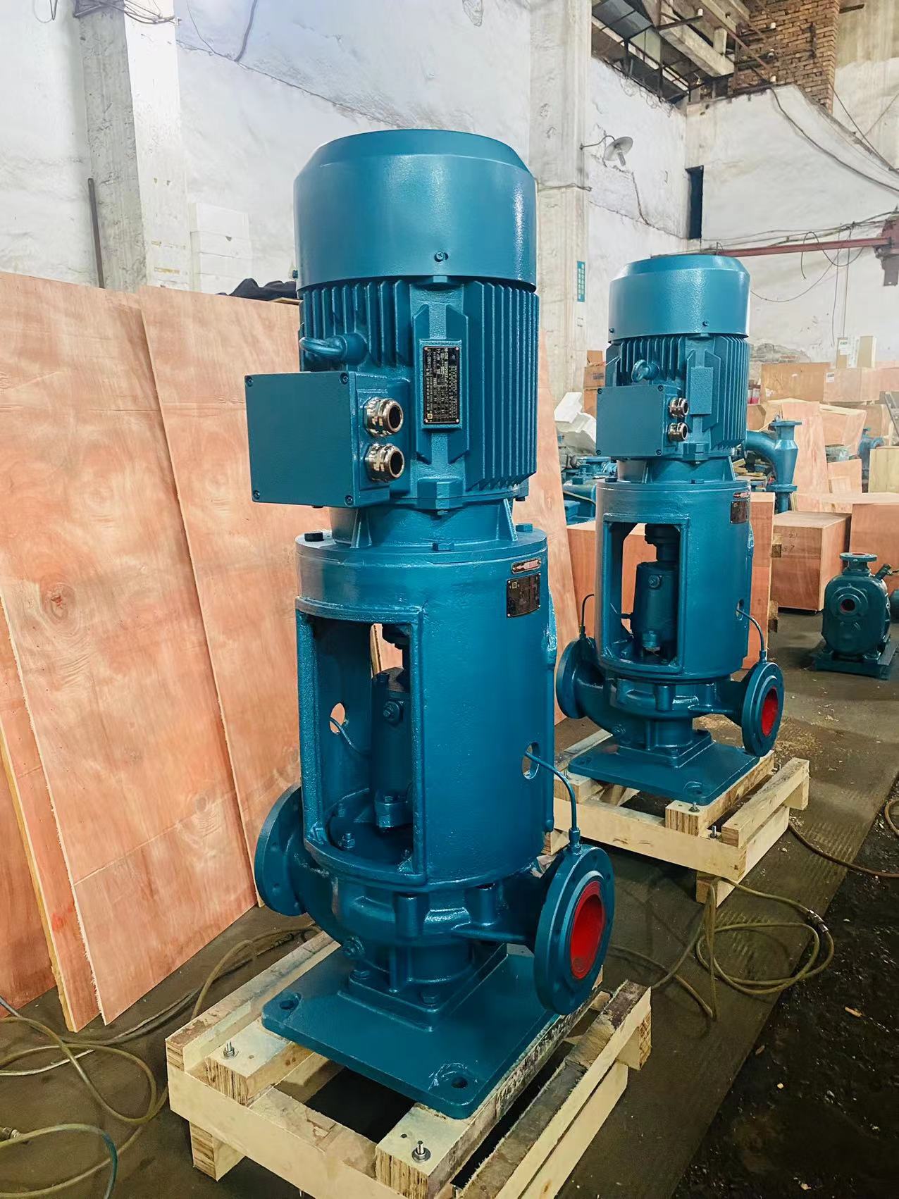
The picture of pump


