Marine pump
-
Marine Fire Pump
-
Marine Emergency Fire Pump
-
Marine Ballast Water Pump
-
Marine Fuel Pump
-
Marine Lubricating Oil Pump
-
Marine Bilge Pump
-
Marine Sewage Pump
-
Marine Fresh Water Pump
-
Marine General Pump
-
Marine Cargo Oil Pump
-
Marine Hand Pump
-
Marine Centrifugal Pump
-
Marine Screw Pump
-
Marine Gear Pump
-
Marine Vortex Pump
-
Marine Ejector Pump
-
Marine Diaphragm Pump
-
Marine Piston Pump
-
Marine Cooling Water Pump
Chemical pump
Industrial Pumps
Other pump
Civil Pump
Submersible Pump
Contact us
Fushi Pump Chongqing Co., Ltd
Address: No. 11, Tianxing Avenue, ShuangQiao Industrial Park, Chongqing,China
E-mail: Sales1@fspumps.com
Tel: +86-23-67956606
Fax: +86-23-67956622
Mobil: +86-19332298771
CYZ-A Marine Sewage Pump
Date:2025-03-07Views:
CYZ-A Marine Sewage Pump
Overview
CYZ-A Series self-priming centrifugal pump, suitable for conveying medium temperature -20℃~80℃. Viscosity ≤100centipoise, solid content of up to 30% following the liquid. Widely used to transport gasoline, kerosene, diesel, kerosene, seawater, fresh water, drainage water. As to the corrosion resistant mechanical seal and a stainless steel parts material Capacity, can then be used for shipbuilding, chemical, pharmaceutical, printing and dyeing, electroplating, brewing, paper, mining, and power. For the tanker or water ships, can be used as a stripper pump. It is self-priming centrifugal pump, it has the advantages of simple structure, convenient operation, stable operation, and easy maintenance, high efficiency, long life, has a strong self-priming Capacity. Pipeline without bottom valve, pump body before work just to ensure there is a certain amount of fluid can be cited. For the tanker or water ships, can be used as a stripper pump, stripping good effect.
Model Explanation 80CYZ-A-32P(B)
80—Inlet diameter 80mm
CYZ—Marine self-priming horizontal centrifugal oil pump
A—Improvement model
32—Head 32m
P—Stainless steel (cast iron if not)
B—Explosion-proof motor (standard if not)
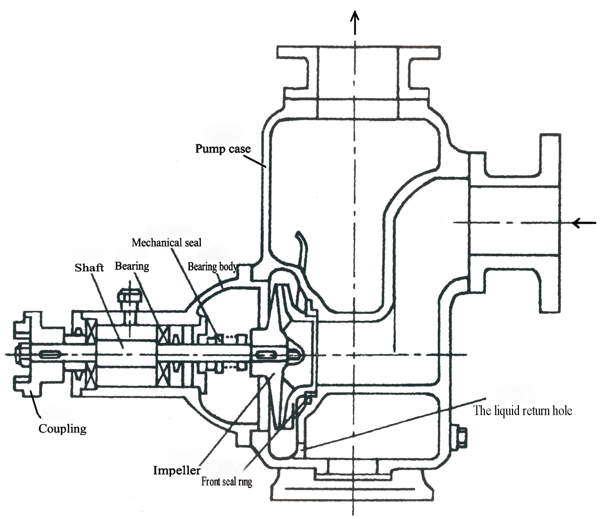
Structural Specifications

Performance Parameter
CYZ-A | 50HZ/2900RPM | 60HZ/3500RPM | 50HZ/60HZ | |||||||
Type | Capacity (m3/h) | Head (m) | Motor Power (kW) | Weight (kg) | Capacity (m3/h) | Head (m) | Motor Power (kW) | Suction (m) | Self-priming performance (min/5m) | Inlet/out dia. (mm) |
25CYZ-A-20 | 3.2 | 20 | 0.75 | 72 | 3.8 | 28.8 | 1.1 | 6.5 | 1.9 | 25 |
25CYZ-A-32 | 3.2 | 32 | 1.1 | 80 | 3.8 | 46.1 | 1.5 | 6.5 | 1.8 | 25 |
40CYZ-A-20 | 6.3 | 20 | 1.1 | 85 | 7.6 | 28.8 | 1.5 | 6.5 | 1.9 | 40/32 |
40CYZ-A-40 | 10 | 40 | 4 | 138 | 12 | 57.6 | 5.5 | 6.5 | 1.5 | 40 |
50CYZ-A-12 | 15 | 12 | 1.5 | 90 | 18 | 17.3 | 2.2 | 6.5 | 2.4 | 50 |
50CYZ-A-20 | 18 | 20 | 2.2 | 98 | 21.6 | 28.8 | 3 | 6.5 | 1.9 | 50 |
50CYZ-A-30 | 20 | 30 | 4 | 140 | 24 | 43.2 | 5.5 | 6.5 | 1.5 | 50 |
50CYZ-A-35 | 14 | 35 | 4 | 145 | 16.8 | 50.4 | 5.5 | 6.5 | 1.5 | 50 |
50CYZ-A-40 | 10 | 40 | 4 | 145 | 12 | 57.6 | 5.5 | 6.5 | 1.5 | 50 |
50CYZ-A-50 | 12.5 | 50 | 5.5 | 160 | 15 | 72 | 11 | 6.5 | 1.4 | 50 |
50CYZ-A-60 | 15 | 60 | 7.5 | 190 | 18 | 86.4 | 15 | 6.5 | 1.3 | 50 |
50CYZ-A-75 | 20 | 75 | 11 | 240 | 24 | 86.4 | 18.5 | 6.5 | 1.3 | 50 |
65CYZ-A-15 | 30 | 15 | 3 | 100 | 36 | 21.6 | 3 | 6.5 | 2 | 65 |
65CYZ-A-32 | 25 | 32 | 5.5 | 165 | 30 | 46.1 | 7.5 | 6 | 1.5 | 65 |
80CYZ-A-13 | 35 | 13 | 3 | 107 | 42 | 18.7 | 4 | 6 | 3.4 | 80 |
80CYZ-A-17 | 43 | 17 | 4 | 156 | 51.6 | 24.5 | 5.5 | 6 | 1.8 | 80 |
80CYZ-A-22 | 40 | 22 | 5.5 | 169 | 48 | 31.7 | 7.5 | 6 | 1.9 | 80 |
80CYZ-A-25 | 50 | 25 | 7.5 | 177 | 60 | 36 | 15 | 6 | 1.5 | 80 |
80CYZ-A-32 | 50 | 32 | 7.5 | 180 | 60 | 46.1 | 15 | 6 | 1.5 | 80 |
80CYZ-A-55 | 60 | 55 | 18.5 | 310 | 72 | 79.2 | 30 | 6 | 1.5 | 80 |
80CYZ-A-70 | 60 | 70 | 22 | 333 | 72 | 100.8 | 37 | 6 | 1.2 | 80 |
100CYZ-A-20 | 100 | 20 | 11 | 258 | 120 | 57.6 | 18.5 | 6 | 1.5 | 100 |
100CYZ-A-40 | 100 | 40 | 22 | 455 | 120 | 28.8 | 37 | 6 | 1.8 | 100 |
100CYZ-A-65 | 100 | 65 | 30 | 620 | 120 | 93.6 | 45 | 6 | 1.8 | 100 |
100CYZ-A-75 | 70 | 75 | 30 | 639 | 84 | 108 | 45 | 6 | 1.8 | 100 |
150CYZ-A-55 | 170 | 55 | 45 | 830 | 204 | 79.2 | 75 | 5 | 1.8 | 150 |
150CYZ-A-65 | 170 | 65 | 55 | 957 | 204 | 93.6 | 90 | 5 | 1.3 | 150 |
150CYZ-A-80 | 160 | 80 | 55 | 986 | 192 | 115.2 | 90 | 5 | 1.2 | 150 |
CYZ-A | 50HZ/1450RPM | 60HZ/1800RPM | 50HZ/60HZ | |||||||
Type | Capacity (m3/h) | Head (m) | Motor Power (kW) | Weight (kg) | Capacity (m3/h) | Head (m) | Motor Power (kW) | Suction (m) | Self-priming performance (min/5m) | Inlet/out dia. (mm) |
100CYZ-A-40A | 100 | 40 | 22 | 520 | 120 | 57.6 | 37 | 6 | 1.8 | 100 |
150CYZ-A-65A | 170 | 65 | 55 | 1138 | 204 | 93.6 | 90 | 5 | 1.2 | 150 |
200CYZ-A-32 | 400 | 32 | 55 | 1205 | 480 | 46.1 | 90 | 5 | 2 | 200 |
200CYZ-A-63 | 280 | 63 | 90 | 1338 | 336 | 90.7 | 132 | 5 | 1.5 | 200 |
200CYZ-A-65 | 350 | 65 | 110 | 1553 | 420 | 93.6 | 160 | 5 | 1.5 | 200 |
250CYZ-A-32 | 550 | 32 | 75 | 1307 | 660 | 46.1 | 110 | 5 | 2 | 250 |
250CYZ-A-50 | 400 | 50 | 90 | 1486 | 480 | 72 | 132 | 5 | 2 | 250 |
250CYZ-A-55 | 450 | 55 | 110 | 1681 | 540 | 79.2 | 160 | 5 | 2 | 250 |
250CYZ-A-75 | 400 | 75 | 132 | 1829 | 480 | 108 | 200 | 5 | 1.5 | 250 |
300CYZ-A-32 | 600 | 32 | 90 | 1608 | 720 | 46.1 | 132 | 5 | 2 | 300 |
300CYZ-A-50 | 500 | 50 | 110 | 1728 | 600 | 72 | 160 | 5 | 2 | 300 |
300CYZ-A-55 | 550 | 55 | 132 | 1995 | 660 | 79.2 | 200 | 5 | 2 | 300 |
Note: power with diesel engine can be used for emergency fire pump.
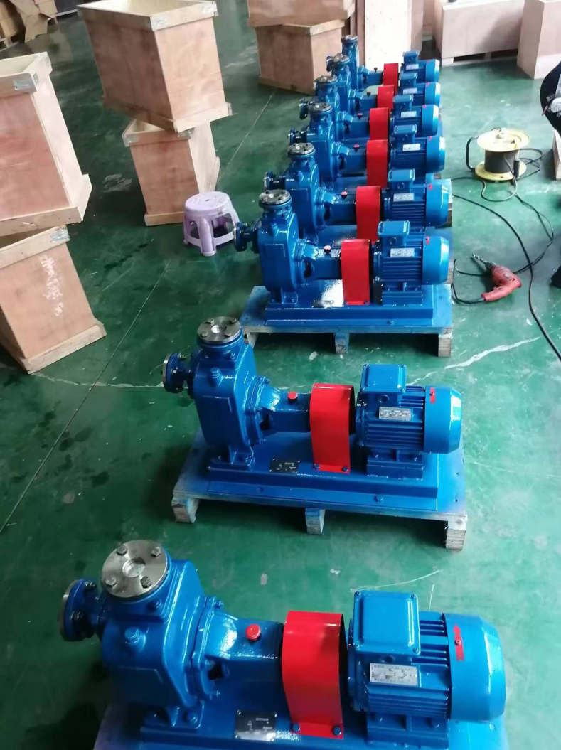
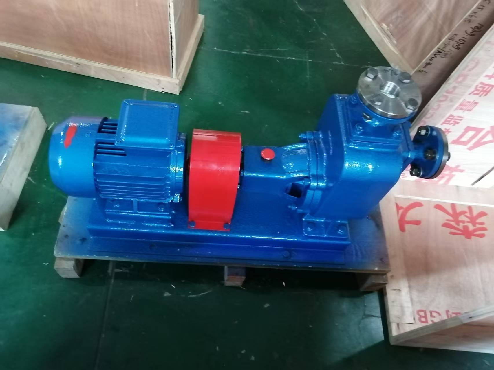
The picture of pump


